
One Video Call, Three Fixes: What Team Inspiration and Team Spyders Saw
How a short test video and one call with Team Inspiration and Team Spyders gave Team Bénin three fixes — entry gap, flat walls, flywheel spacing — and our final FGC 2026 build.
In this article
You know that feeling when you've looked at something so many times that you stop seeing it? Like a crooked picture in your own house that every visitor notices on day one?
That was us and our robot after Version 2.
The Call
After our Version 2 test, we had video calls with two experienced teams: Team Inspiration and Team Spyders. Before the call, we sent them our test video and photos. That's it. No long report, no 3D files. Just a short phone video and a few pictures.
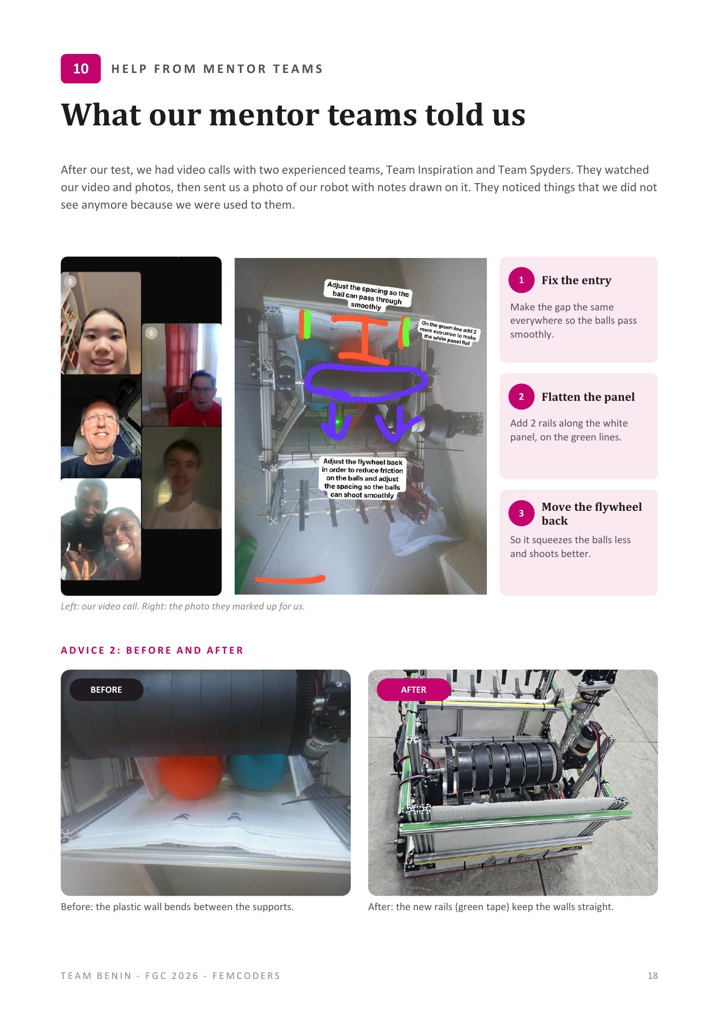
They watched it. Then they sent us back a photo of our own robot with notes drawn all over it: orange lines, green marks, purple arrows, little text boxes. It looked like a coach's tactics board, except the players were our flaps and our flywheel.
In a few minutes, they noticed things we didn't see anymore, because we were used to them.
Honestly, it was a bit humbling. And it was one of the best moments of our season.
Fix 1: Fix The Entry
Their note: adjust the spacing so the ball can pass through smoothly.
Remember frame 5 of our test video, where a ball stays stuck at the flaps? The mentor teams spotted the reason right away: the gap at the entry is not the same everywhere. In some places it's perfect, in others it's a bit too tight. A ball arriving at a tight spot hesitates.
The fix: make the gap the same everywhere, so every ball meets the same space no matter where it arrives across the 50 cm width.
This connects to a lesson we keep relearning: start with the ball. A 100 mm foam ball decides the size of every gap. If the gap changes along the entry, the ball notices, even if we don't.
Fix 2: Flatten The Panel
Their note: on the green lines, add 2 more extrusions to make the white panel flat.
This one is my favourite, because it's so simple. Our plastic side wall was only held at a few points. Between those supports, it bent inward. Not a lot. A few millimetres. But a few millimetres in the wrong place makes the path narrower, and the balls slow down when they squeeze through.
The fix: add 2 rails along the white panel, exactly where they drew the green lines.
We did it. Here's the before and after:
BEFORE: the plastic wall bends between the supports. You can see the curve in the photo once you know to look for it.
AFTER: the new rails (we wrapped them in green tape so they're easy to spot) keep the walls straight.
Two rails from the kit. That's the entire fix. And the balls now roll through without slowing down.
As the electrical lead, I also like this fix for another reason: two more rails means two more places to tie my cables. No loose cables on my robot. Ever.
Fix 3: Move The Flywheel Back
Their note: adjust the flywheel back in order to reduce friction on the balls, and adjust the spacing so the balls can shoot smoothly.
Our shots in Version 2 were weak. Our instinct was that the flywheel needed more power. The mentor teams said the opposite: the flywheel was pressing the ball too hard.
Here's the physics as we now understand it. A flywheel throws a ball by squeezing it a little and spinning it out. A little squeeze gives grip. Too much squeeze turns into friction: the ball gets crushed, rubs against the wheel and the walls, and loses the speed the wheel tried to give it.
The fix: move the flywheel back, so it squeezes the balls less. More space, less friction, better shots.
This one changed how we think. In our "What we learned" list, it became lesson 4: pressing harder doesn't shoot faster. The gap is as important as the motor.
Why One Video Was Enough
We want to underline this for other teams, because it surprised us: a short phone video was enough for two teams on the other side of the world to understand our robot and help us in one call.
This only worked because of a habit we built all season: we film every test. Not just the good ones. If we had only had nice photos of our robot standing still, nobody could have seen the ball hesitating at the entry or the shot losing speed. The problems only exist in motion. So you have to show the motion.
Tips if you want help from another team:
- Film from above AND from the side.
- Use real balls, at real speed.
- Keep it short (under a minute is perfect).
- Include the failures. That's what they need to see.
- Say clearly what you think the problem is, and then listen when they say it's something else.
Thank You
To Team Inspiration and Team Spyders: thank you for giving your time to a team you had never met. You looked at our robot with fresh eyes and gave us three fixes that made it better. This is what the FIRST spirit means to us. We hope to meet you in Incheon, and we hope we can do the same for another team one day.
The Final Build, With The Fixes Applied
Here's our competition robot after the call:
Frame and wheels. Our frame is made of aluminium rails and fills the 50 cm cube. Because there are rails on every side, we can attach parts and move them easily, which is exactly what made the "add 2 rails" fix so fast. We use tank drive with one motor per side: both sticks forward to go straight, one stick at a time to turn. We put the heavy parts low (battery, hubs and drive motors near the floor) so the robot doesn't tip over. Version 1 taught us that.
Intake and hopper. Three shafts of black rubber flaps cover the whole front of the robot. One motor turns all three with a chain. Because the flaps cover the whole width, the robot catches 2 to 3 balls at a time. The hopper holds up to 25 balls: the balls go up a sloped panel, then roll on a clear floor to the feeder. Extra rails keep the plastic walls flat (thank you again, mentor teams).
Flywheel and feeder. Our flywheel is a row of soft black wheels on one shaft, as wide as the robot, turned by one motor. Under it, a shaft of flaps called the feeder pushes the balls up into it. The flywheel can shoot 2 to 3 balls at once. The feeder has its own motor, so the flywheel keeps its speed and the driver decides exactly when to shoot.
Climber. A mast holds a roller made of two cone-shaped wheels facing each other. Together they form a V that sits on the round Brace pipe. We drive under the Brace, place the roller on the pipe, and its motor pulls the robot up.
Rule check: the robot must come off the Brace with the power off. We check this on our climber before every inspection. We don't want any surprise at inspection in Korea.
Next entry: the electrical system and the code. Six motors, zero sensors, and the one number we set on the flywheel: 2600.
Takeaway For Other Teams
Ask for help early, and make it easy to help you: a short video of a real test is worth more than a long explanation. And if another team ever sends you a marked-up photo of your robot, frame it. Ours is in our engineering notebook.