
Six Motors, Zero Sensors, One Number: 2600
Team Bénin's FGC 2026 wiring and code: two hubs, six motors, REV Blocks exported to Java, a velocity-controlled flywheel at 2600 and the controller map — plus the bug we still need to fix.
In this article
This entry is written by Richmond, who writes the code, and Arsène, who wires everything the code talks to. When the robot does something weird, the first question is always: code or wires? This entry is our answer to both.
Part 1: The Electrical System (Arsène)
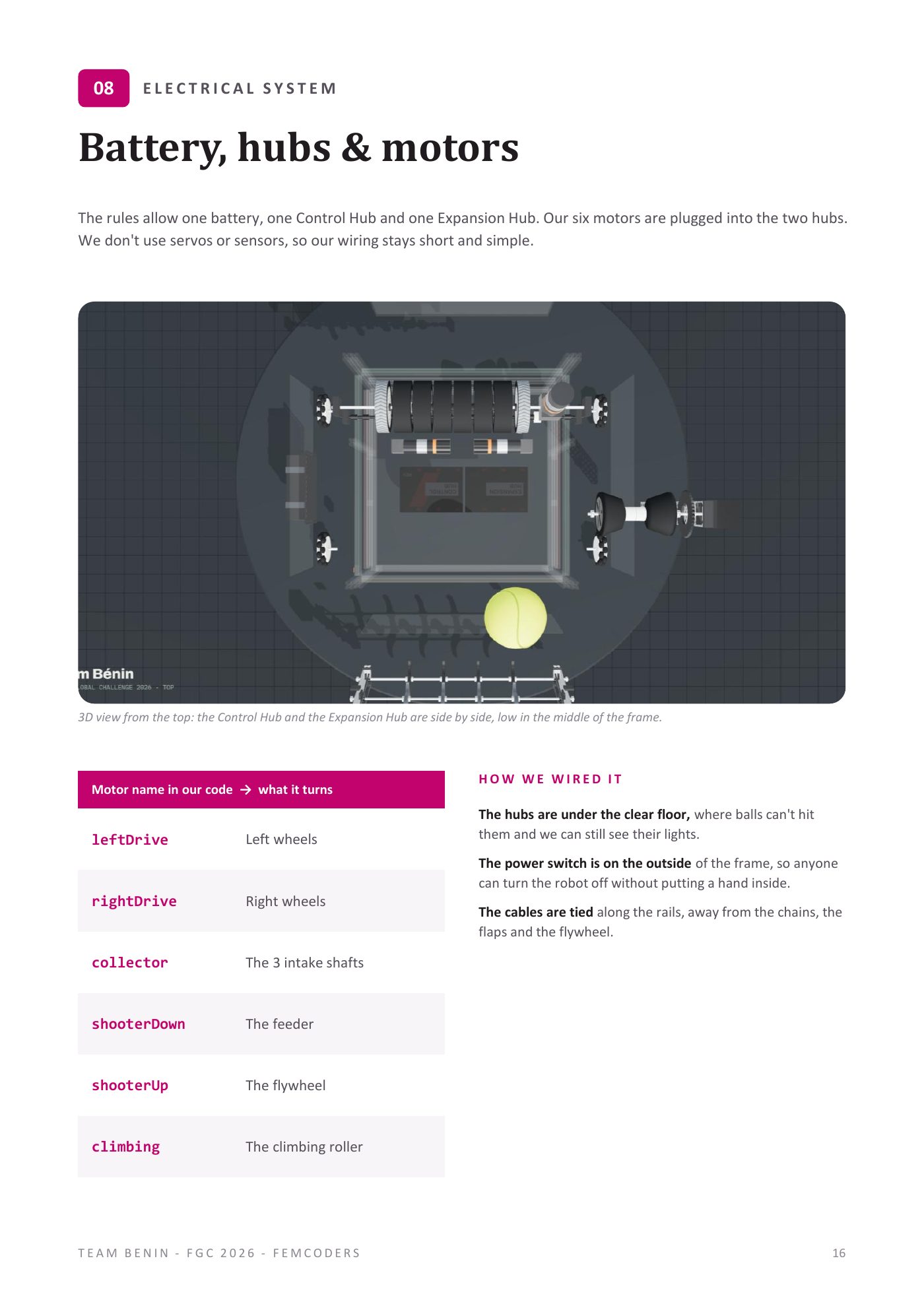
The rules allow one battery, one Control Hub and one Expansion Hub. That's the whole brain and heart of the robot. Our six motors are plugged into those two hubs.
And here's something that surprises people: we don't use any servos or sensors. Zero. No colour sensor, no distance sensor, no touch sensor.
Why? Because of our "few things done well" rule. Every sensor is another cable, another connection that can come loose when a robot crashes into us, another thing to debug in the pit with five minutes left. Our robot's job is simple: collect, store, shoot, climb. The driver's eyes do the sensing. So our wiring stays short and simple, and short simple wiring is wiring that survives a match.
Our six motors and what they turn (these are the exact names in our code, and the exact labels on the cables):
- leftDrive — left wheels
- rightDrive — right wheels
- collector — the 3 intake shafts
- shooterDown — the feeder
- shooterUp — the flywheel
- climbing — the climbing roller
Naming tip for other teams: name motors by what they DO, not by where they're plugged. "Port 2" means nothing at 2 a.m. "collector" means something.
How We Wired It
The hubs are under the clear floor. Balls can't hit them there, and because the floor is clear, we can still see their status lights. If something goes wrong in a match, a quick look tells us if the hubs are alive.
The power switch is on the outside of the frame. Anyone (a teammate, a referee, a field volunteer) can turn the robot off without putting a hand inside a machine full of spinning flaps. Safety first, and it's also faster.
The cables are tied along the rails, away from the chains, the flaps and the flywheel. A cable caught in a chain doesn't just stop your robot. It can rip a connector out and end your match. So: rails, ties, and no loose cables. On my robot. Ever.
Bonus from the mentor-team fixes: the two extra rails we added to flatten the walls also gave me two extra places to tie cables. Everybody wins.
Part 2: The Code (Richmond)
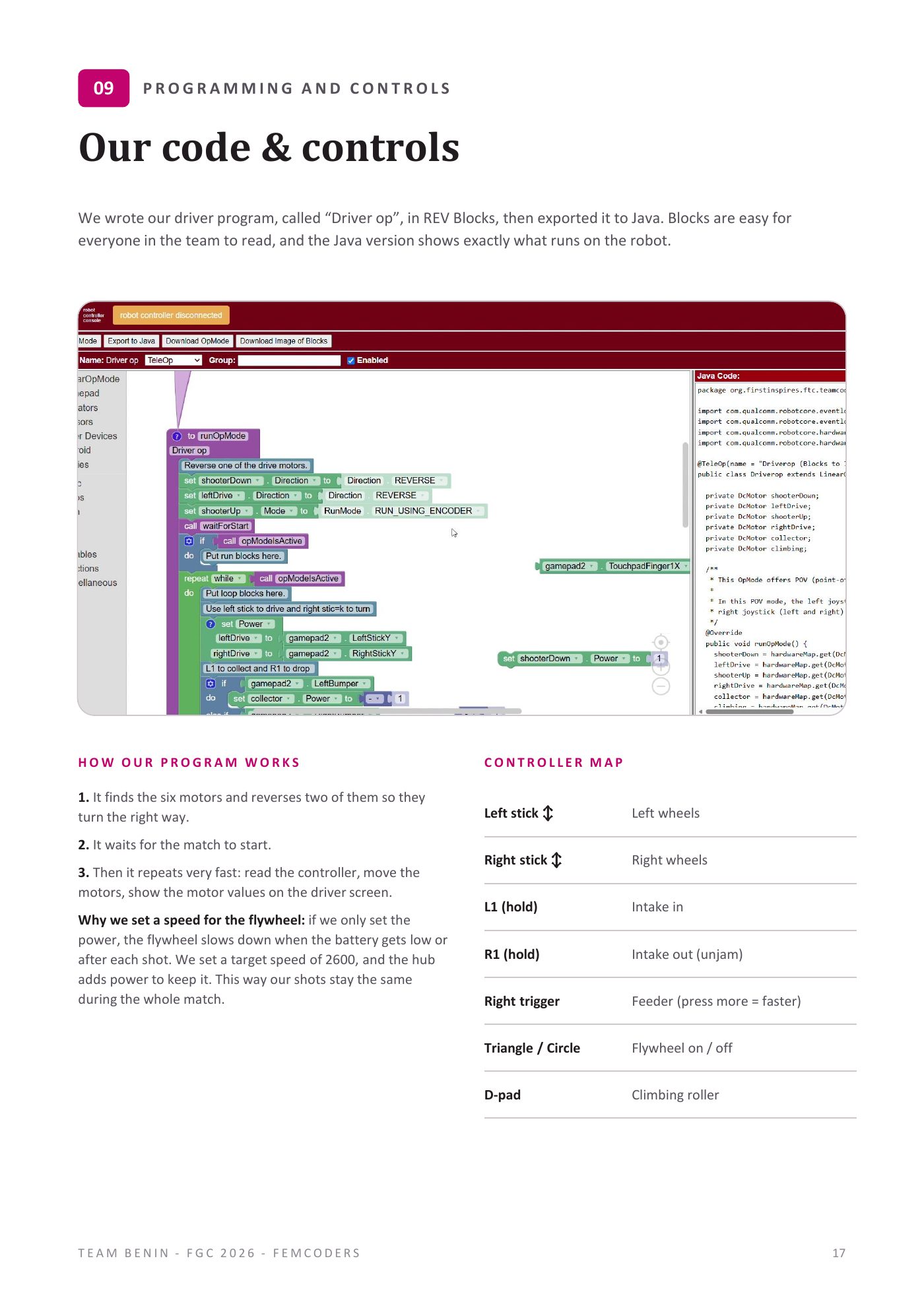
We wrote our driver program, called "Driver op", in REV Blocks, then exported it to Java.
Why both?
Blocks are easy for everyone on the team to read. Ten people, ages 7 to 18, not all of them programmers. With Blocks, Melvit can look at the program and see "oh, left stick moves leftDrive." Amos can check what the right trigger does. Even Ayman can point at a block and ask what it does. Code that the whole team can read is code the whole team can help debug.
The Java version shows exactly what runs on the robot. When Simon or our mentors want to check something precisely, the Java is right there. Blocks for the team, Java for the truth.
How Our Program Works, In Three Steps
- It finds the six motors and reverses two of them, so they turn the right way. (Motors mounted on opposite sides of a robot spin in opposite directions. If you don't reverse one drive motor, "go forward" becomes "spin in a circle.")
- It waits for the match to start.
- Then it repeats very fast, again and again until the end: read the controller → move the motors → show the motor values on the driver screen.
That's it. No fancy state machines. A simple loop that's easy to understand and hard to break.
The Star Of The Show: 2600
OK, here's the part we're proudest of, technically.
Our first version of the code just set the flywheel's power: "flywheel, go at 100% power." Simple, right?
Problem: power is not speed. When the battery gets low near the end of a match, 100% power gives a slower spin. And every time the flywheel shoots a ball, the ball steals some energy and the wheel slows down for a moment. So with power-only control, our shots changed during the match. Strong at the start, weaker at the end. Strong for the first ball, weaker for the second.
For a robot whose strategy is "go to the same spot and shoot the same way every time," that's a disaster. The practised shot only works if the flywheel speed is always the same.
The fix: instead of setting a power, we set a target speed. We put the flywheel motor in RUN_USING_ENCODER mode and gave it a target velocity of 2600. The encoder measures how fast the wheel is actually spinning, and the hub automatically adds power when the wheel slows down (after a shot, or when the battery drops) to bring it back to 2600.
Result: our shots stay the same during the whole match. First ball, last ball, full battery, tired battery. Same 2600.
Why 2600 and not 3000? The engineering notebook records 2600 as our working target. We will check the setting again on the competition field. Too slow and the ball doesn't reach the opening. Too fast and it flies over. 2600 was our sweet spot. In Korea, on the real field, we'll test it again and adjust if needed. One number to change, one place in the code.
The Controller Map
Here's how our robot is driven:
Left stick (up/down) — left wheels Right stick (up/down) — right wheels L1 (hold) — intake in R1 (hold) — intake out (to unjam) Right trigger — feeder (press more = faster) Triangle / Circle — flywheel on / off D-pad — climbing roller
A few design choices here:
The intake is "hold", not "toggle". You hold L1 to collect and let go to stop. That way the driver always knows the state of the intake: finger on button = intake running. No "wait, is it still on?"
R1 reverses the intake. When a ball jams at the entry, one tap of R1 spits it back out. It's there for exactly the kind of jam we saw in frame 5 of our Version 2 test video.
The feeder is on a trigger, not a button. The trigger is analogue: press a little for a slow feed, press hard for a fast feed. So the driver can shoot balls one at a time when aiming carefully, or empty the hopper quickly when the path is clear.
The flywheel has its own on/off. It spins up separately from the feeder, so the driver can bring it to 2600 while driving, before arriving at the shooting spot. No waiting.
THE BUG WE'RE HONEST ABOUT
There is one known bug, and we put it in our notebook because judges should see we know our robot, problems included.
Right now, D-pad up and D-pad down both turn the climber the same way. Down should turn it backwards, so we can lower the robot or correct a bad position on the Brace. It's on our "next steps" list, and we plan to fix it before our first match. At the time of our notebook, the D-pad issue was still on our next-steps list. We planned to test a correction before competing.
We'll also try something new: two controllers. Melvit drives with one, and Amos controls the intake, the feeder and the flywheel with the other. That splits the work: one brain on driving, one brain on the ball path.
Next entry: 2 minutes 30 seconds. Our match plan, minute by minute, and who does what on the drive team.
And name your motors by their job. Future-you will say thank you.
Takeaway For Other Teams
If your shooter uses a flywheel, control its speed, not its power. Use the encoder (RUN_USING_ENCODER) and a target velocity. Your shots will stop getting weaker as the match goes on, and you'll be able to tune your shot with one single number.